Welcome to the blog
Hello there! My name is Michael and I am an IT guy from Carinthia. I like to play around with technology and learn new things. Idea behind this blog is to provide you articles about projects, ideas, etc. Inspired by Bruno Hautzenberger’s web site (Thanks Bruno!), the blog is static HTML using Jekyll provided and hosted by GitHub Pages. This makes blogging fun, because using #Markdown makes editing and updating is easy.
Contact and other profiles
Twitter Instagram LinkedIn Company WebPage Github michael(at)strali.solutions
Feel free to reach out to me!
Posts
Flauschi - the WLED powered Ghost
2021-12-17 #Blog | #IoT | #WLED | #kidstech
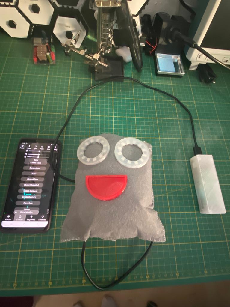
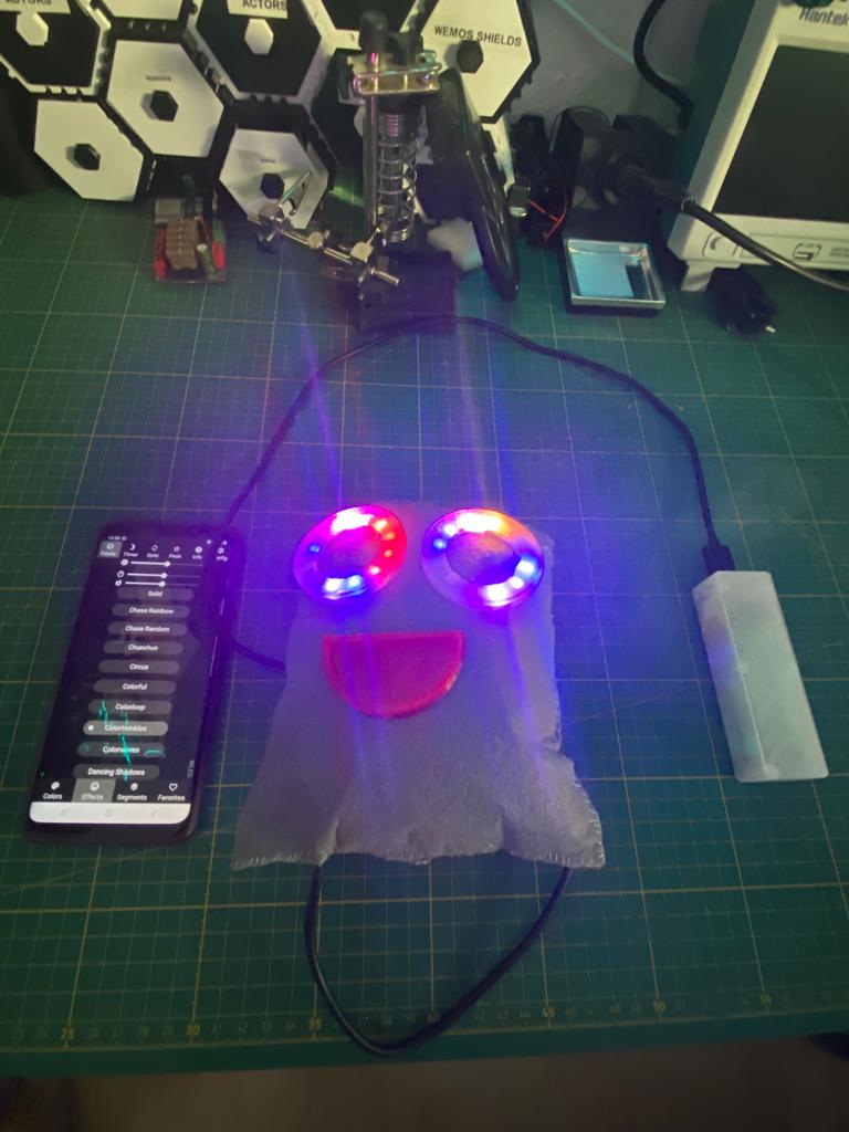
After assembling a WLED powered XMas lighting, my daughter Tamara asked me if we can do something with LEDs. So, after searching in the IoT surprise box, we found LED rings and then the idea come up to create Flauschi, the Ghost with the shining eyes.
Thanks to the WLED library it simple to control the light of Flauschi’s eyes and you can integrate Flauschi into your home automation, etc. More information on WLED you can find here.
What hardware do you need?
- ESP8266 / ESP32 board of your choice (would recommend to use Wemos Mini)
- Wires, solder and soldering iron
- 2 pieces of LED rings
- 3d printer and a bit of red and transparent filament
- Felt sheets
- Needle and thread
- Super glue
- Cotton wool
- Hot glue gun
Creating Flauschi
- Cut 2 felt sheets in form
- Position the LED rings as eyes, cut holes accordingly and move the wires into the holes
- Print with transparent filament the diffusers for the LEDs. Here you can find a version for a 12 LED ring
- Print with red filament the mouth. Here you can find the mouth
- Solder the led rings and the ESP together according to wiring. Keep an eye on the DIN and DOUT port usage of the LED ring, otherwise it won’t light. The Standard PIN for the digital control signal of the LED is PIN 2 on the ESP. Solder the 5V to VCC and GND to GND and also the data PIN.
- Flash WLED => follow the instructions. Recommended method is to flash it directly via browser. This is easy going :)
- After Flashing, connect to the WLED-AP and configure your Wifi settings and then test the functionality
- If everything works, take a hot glue gun and fix the ESP and the wiring on the back of the felt sheet. Add also an usb cable and fix it with the hot glue => this you can use as power connection via USB (other options possible of course). Then glue the diffusers on the LED shields and glue both on the felt.
- Take the printed mouth and glue it on the felt
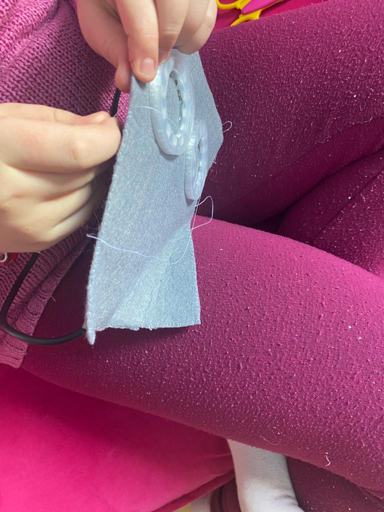
- Now it is time for sewing the two felts together and leave on side open for filling with cotton wool
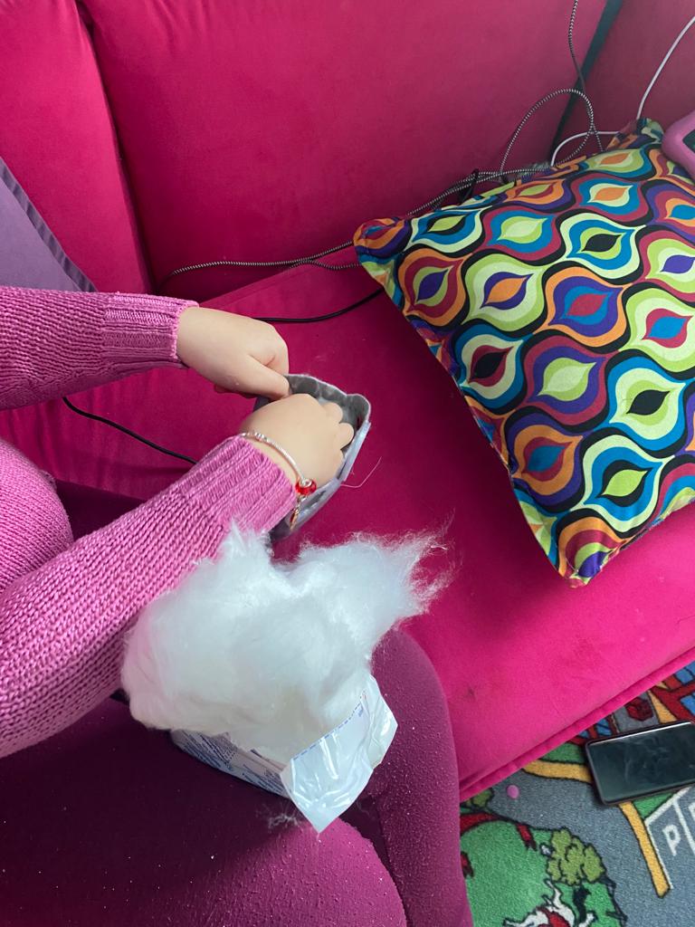
- Fill Flauschi with cotton wool
- Sew the last side and ensure that the USB cable comes out of Flauschi
- Connect the USB cable to a power source (Powerbank, etc.) and check if the eyes are shining bright
- Congratulations your Flauschi is alive
In order to double up the speed and enjoying building things together, my daughter did the creative and material work and I did the soldering and flashing part. It was a great time building Flauschi together.
Here you’ll find a few impressions. Hope you like it and now it’s your turn to create your personal Flauschi!
Smart Watermeter reader aka AI-on-the-edge-device (by jomjol)
2021-01-12 #Blog | #AI | #Watermeter
Every once a year our local village water department sends us a snail mail to read the measure of our water counter and send them back. And every year, I think, why the hell is this necessary, if there are technical solutions out there which can handle this, …but that’s another story, however.
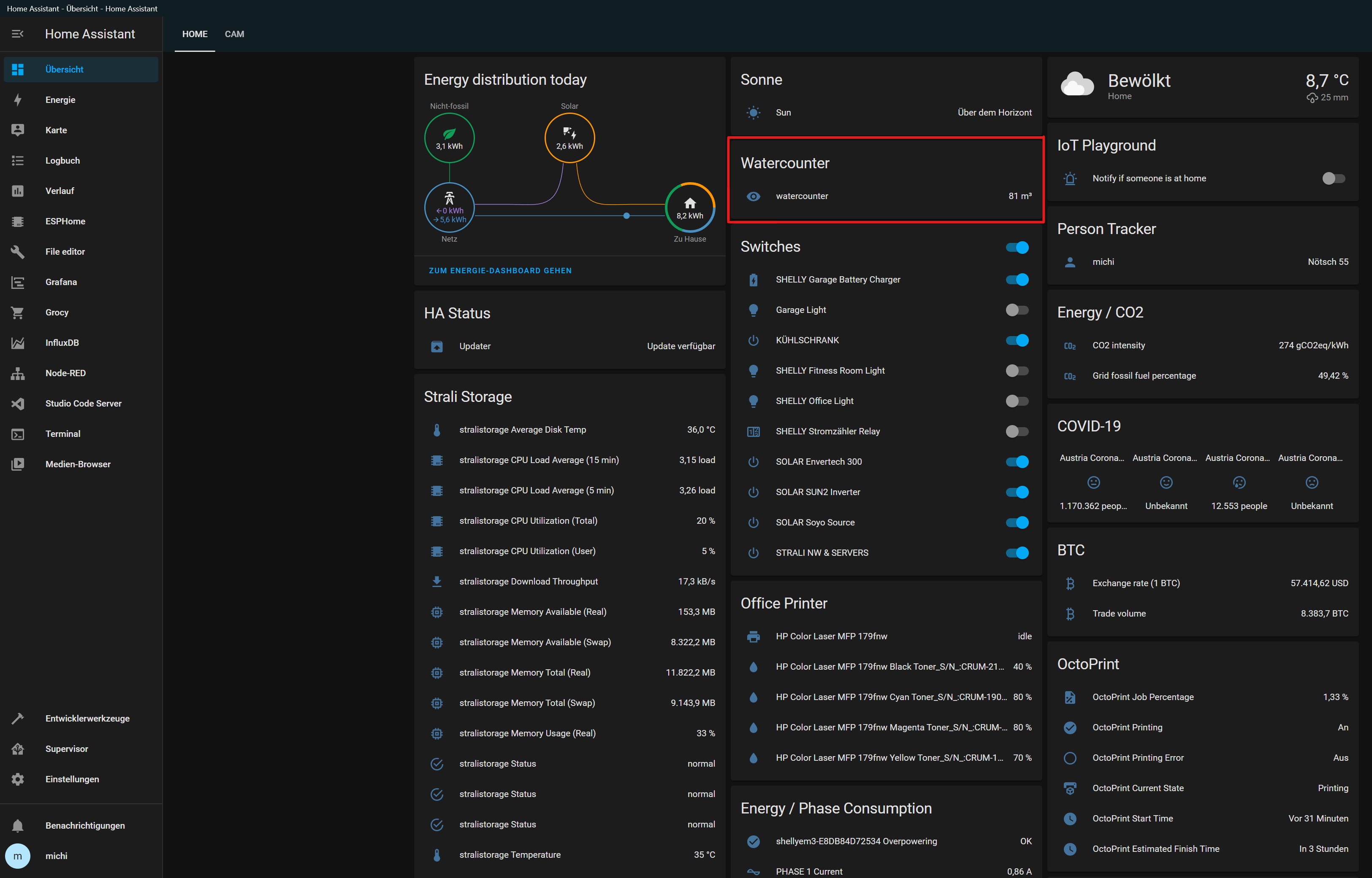
Next time, we can do this a little bit easier directly in our Home Assistant.
Thanks to the great effort of @jomjol there is an open source solution in order to read out our digital and even anolog meters (even reading out old energy meters should be possible)!
What hardware do you need?
- ESP32 AI Thinker CAM
Platform
You need one running MQTT broker. You can find a guide here.
Architecture overview
Before we come to the implementation of the client and the gateway, let’s check what we would like to build.
How does it work?
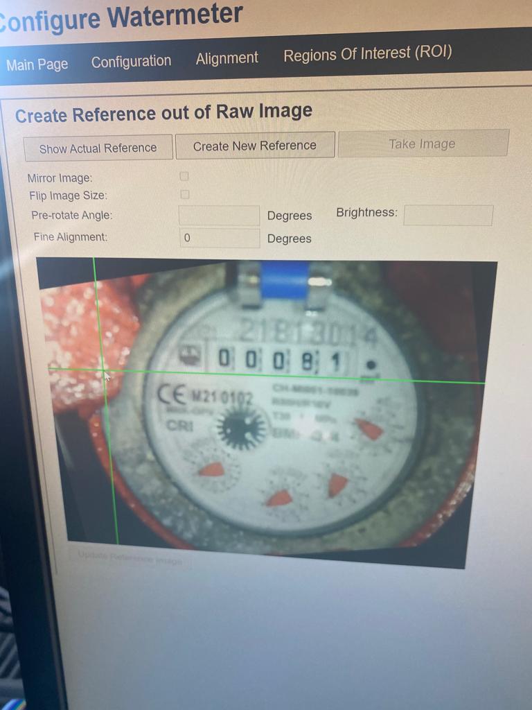
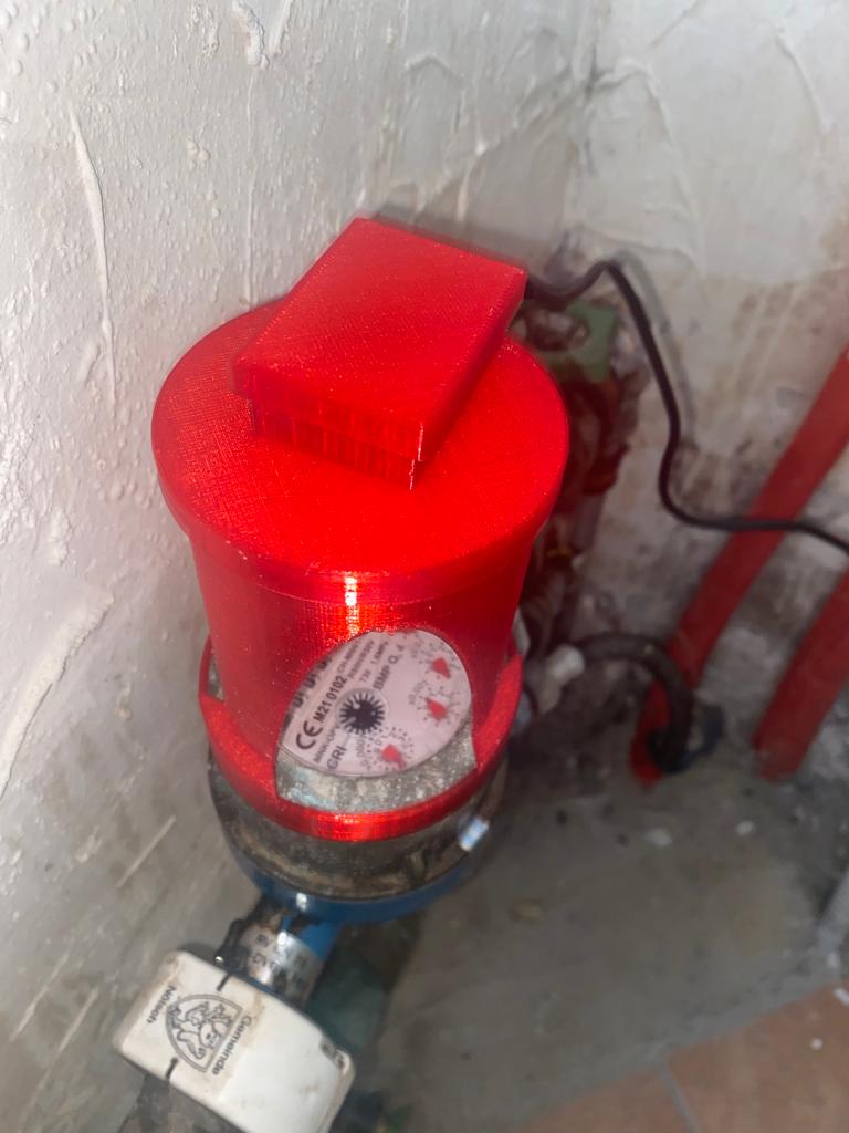
The ESP32 cam in the 3d printed housing is mounted on top of the watermeter.The device is using a trained neural network in order to interpret the numbers. After setup and calibration of the firmware the cam will push the data through the MQTT channel in a defined interval. All you need in order to setup and configure can be found here.
How does it look like?
Protect streaming using SecureToken in Wowza Streaming Engine - .NET Sample Code
2021-04-20 #Blog | #Wowza | .NET
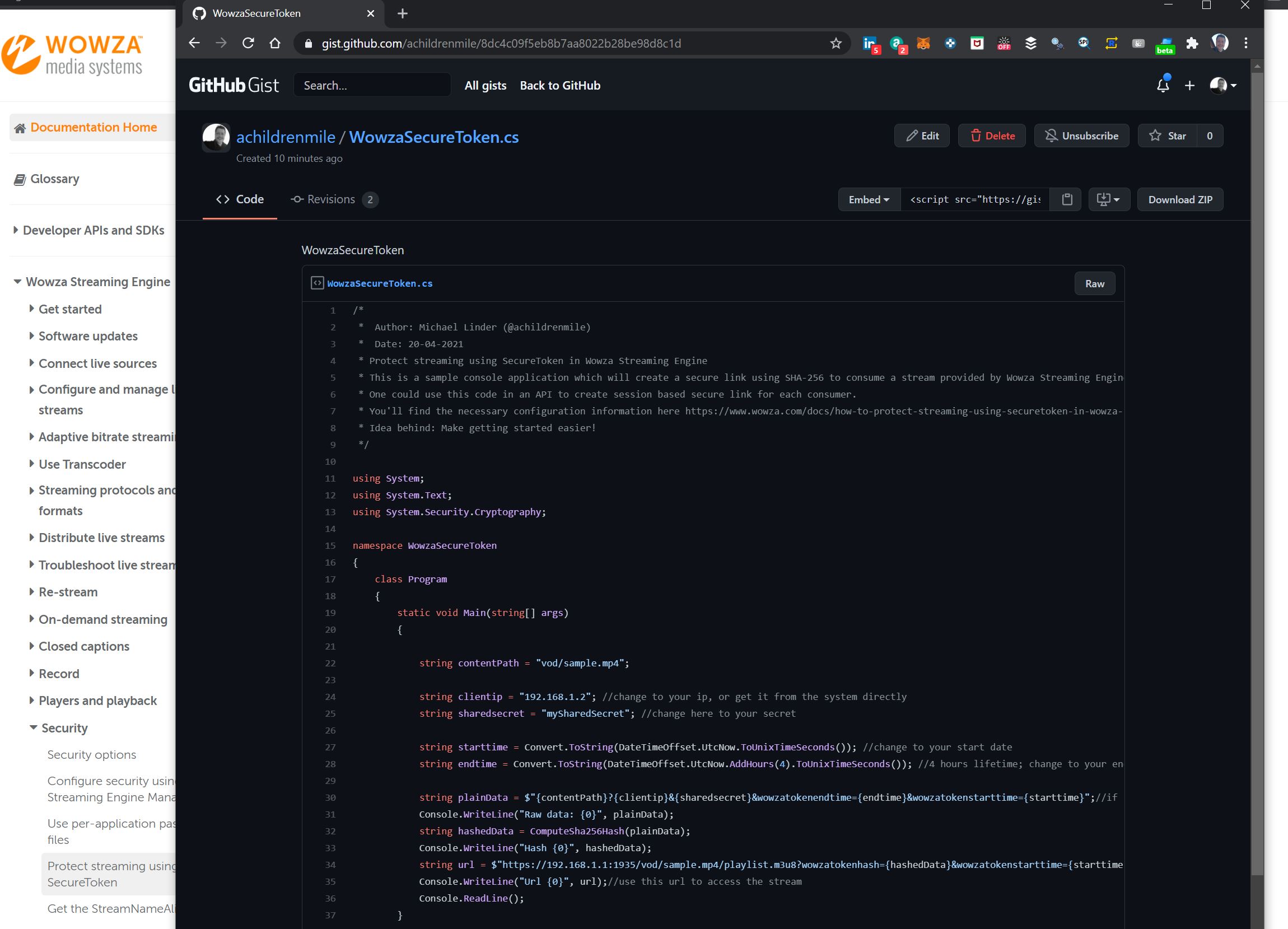
Recently, there was the need to protect streams in Wowza Streaming engine using Secure Tokens. While there is an article explaining the detailed handling, there is no useful source code sample out there. To make you the getting started easier you can find a working .NET sample code here!
Hope this helps you to get started quickly to secure your streams :)
Getting Started with PSOC6
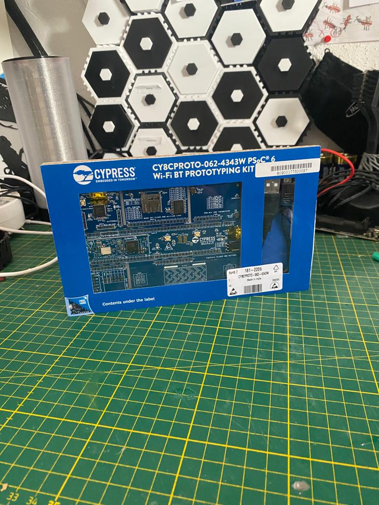
In this post you’ll get to know how to setup the development environment for #PSOC6 from Infineon and execute the “Hello world” program.
What is PSOC6?
Before we start, let me quickly introduce you what PSOC6 is and what is used for.According to Infineon, the PSoC 6 family is built on an ultra-low-power architecture, and the MCUs feature low-power design techniques to extend battery life up to a full week for battery powered applications. The low power consumption makes the MCU interesting for gathering sensor data and many more applications. Normally in my projects I am using the Espressif MCUs. However, in the upcoming monthS, I’ll build also some use cases with PSOC6 and compare the architectures. For more information about PSOC6, you can visit this page.
What hardware do you need?
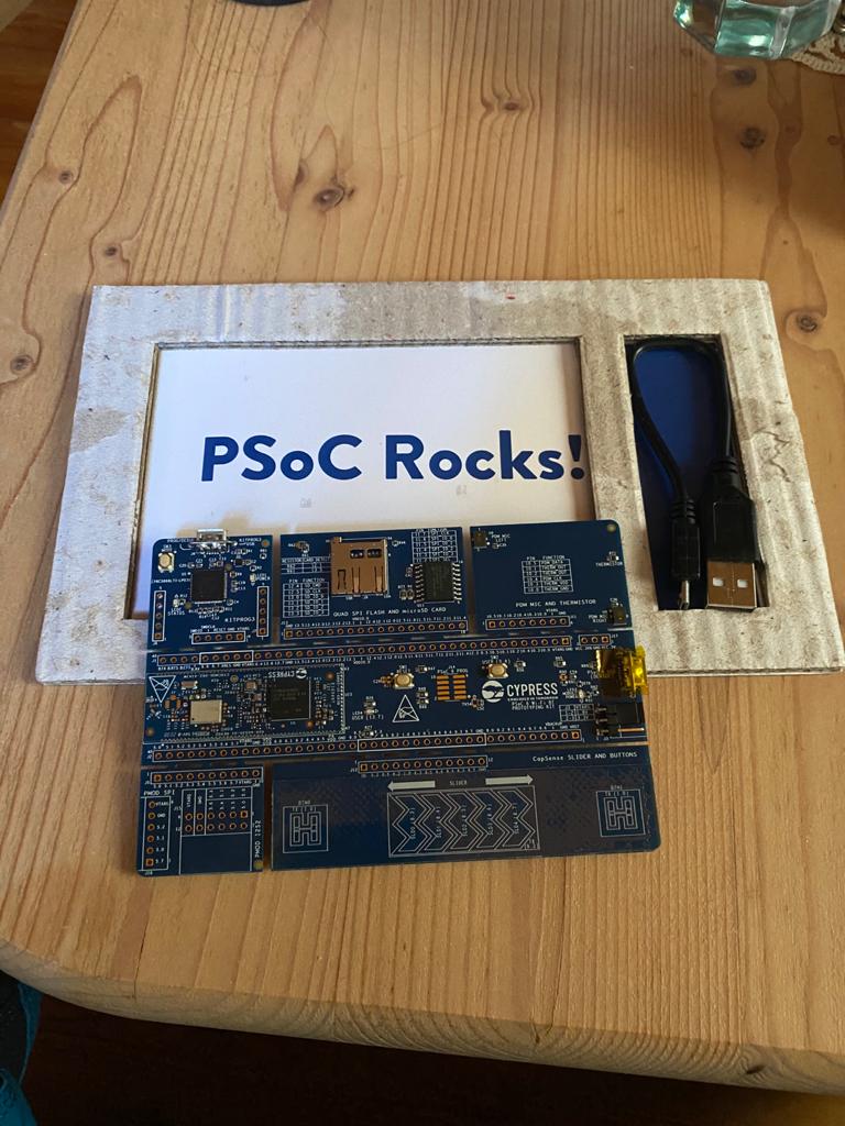
- PSOC 6 WiFi BT Protoyping Kit CY8CPROTO-062-4343W for around 30 €. I bought this from RS components - here
- A notebook or PC to install the drivers and the Modus Toolbox for programming the MCUs
Installation of Modus Toolbox
- open a browser and navigate to www.cypress.com/CY8CPROTO-062-4343W
- download the Modus Toolbox software
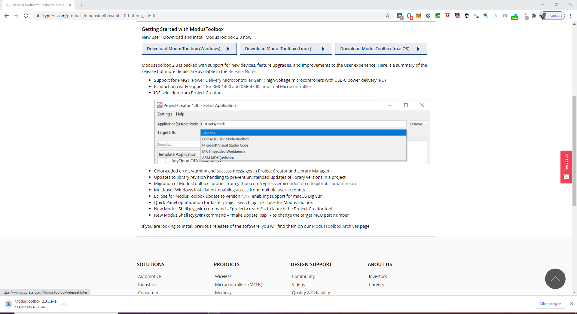
- Register of you do not have an account
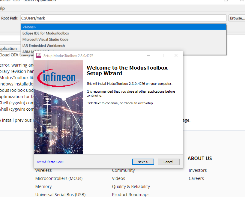
- Start installation, follow the installation steps and then restart your PC
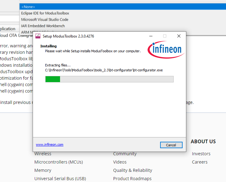
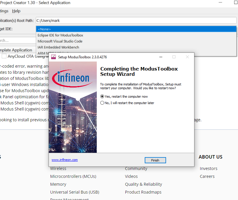
Connect the PSOC6 and start the “Hello World” programm
- Ensure that jumper J3 is at position 2-3 to select 3.3V
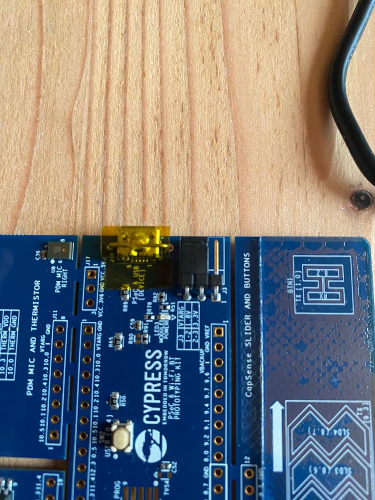
- Connect the protoyping kit with the PC
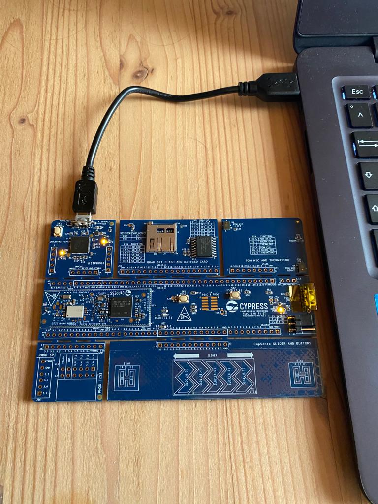
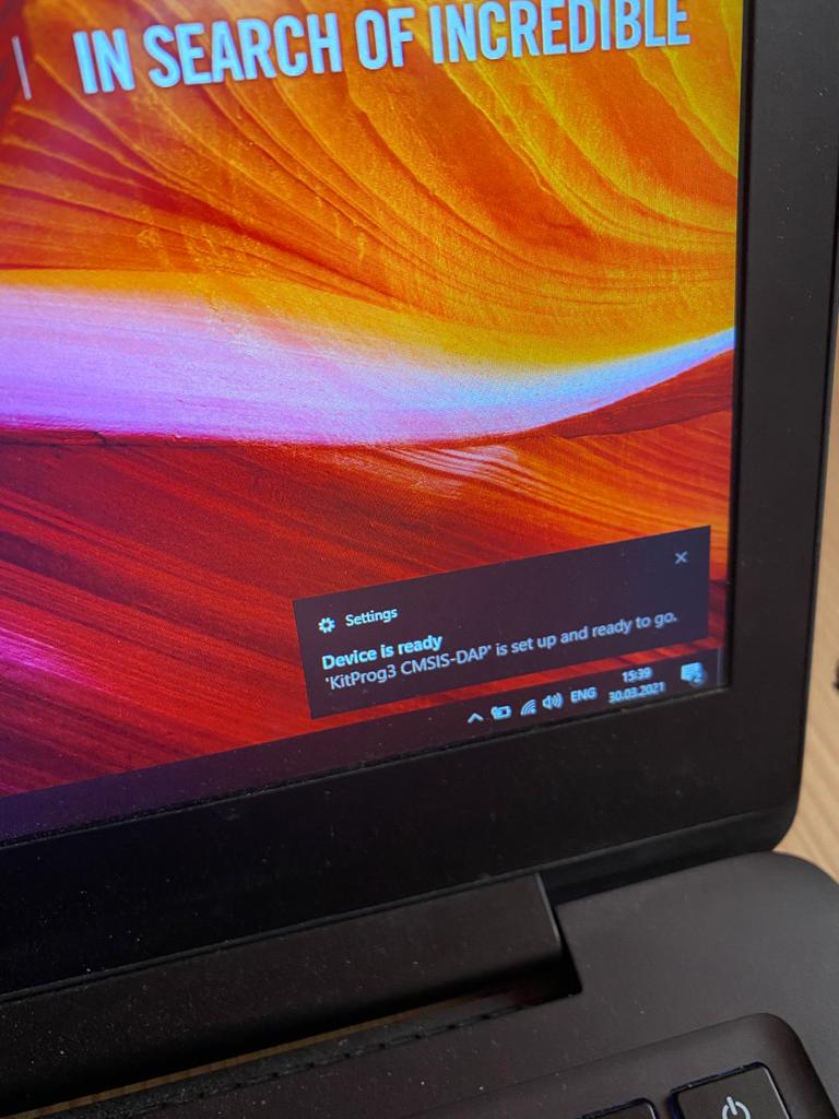
- Wait until the driver is installed
- Check the COM port in the Device Manager
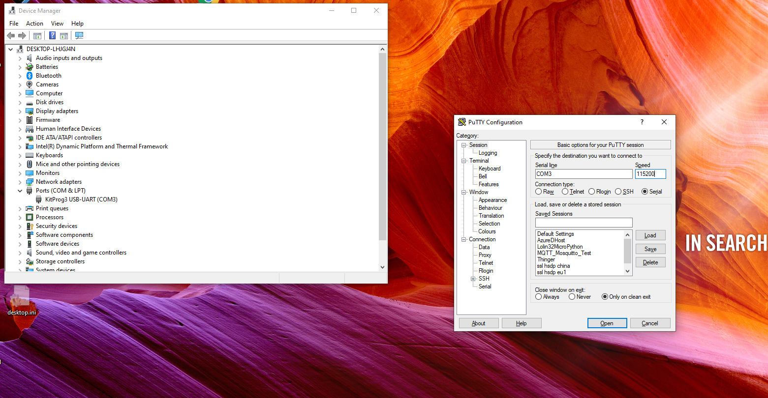
- Open a terminal programm, like e.g. Putty
- Connect to the COM port with baud rate of 115200
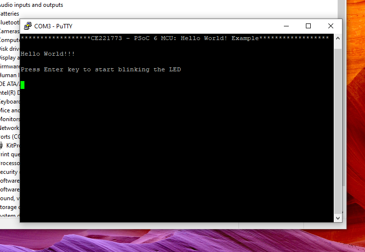
- Press Switch 1
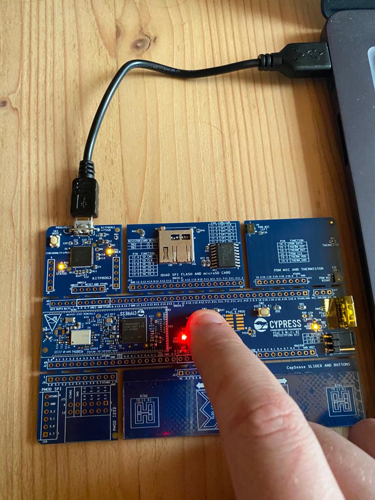
- Press Enter and see the port LED blinking
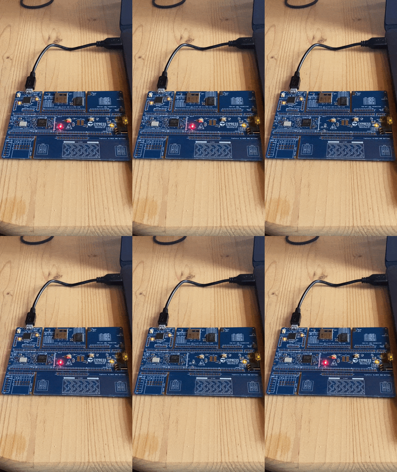
Congratulations, you successfully finished the PSOC6 and IDE setup!
Meshtastic - Your own private mesh network
2021-03-23 #Blog | #Meshtastic
Did you ever ask yourself, how to build a reliable and secure mesh network, which works without Internet access and gives you complete freedom and privacy in order to exchange messages in a secure way?
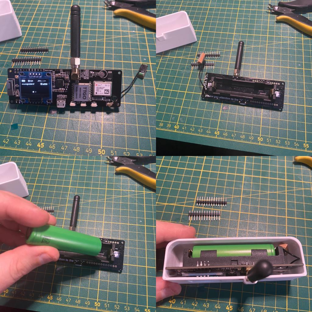
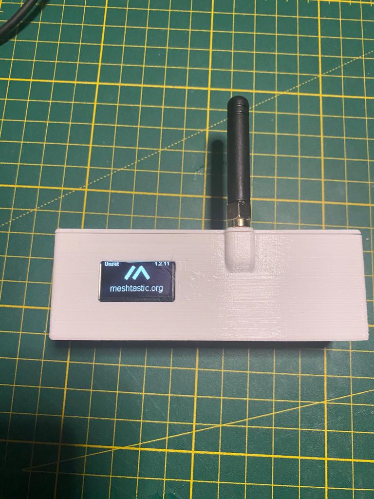
By searching for answers and technical possiblities around the #LoRa technology, I came across the #Meshtastic project. The project is complete #opensource, comes with a great community, Android app and supports several #LoRa GPS boards like the TTGO T-Beam or the Heltec LoRa 32.
The smartphone communication to the meshtastic mesh node happens via bluetooth. The sender will send the message. The mesh node will use the #LoRa band in order to communicate with the mesh nodes, in order to deliver the message to the recipient using the app and bluetooth.
This is a really cool project. I can highly recommend to have a look at it.
LoRa Wan Gateway and The Things Stack
2021-03-13 #Blog | #LoRaWan | #LoRaWanGateway
In the post “Lora MQTT Gateway” it was shown how to create a LoRa application scenario using 2 TTGO’s as gateway and sender and consume messages using #MQTT. As LoRa offers a lot of possibilities and once you dig in deeper, you’ll come to TheThingsStack network and this offers a lot of ideas and possibilities. The Things Stack project is community driven and a great way to make the #LoRaWan technology public available. So, the decision was made to place a public #LoRaWanGateway in Nötsch im Gailtal.
What is LoRaWan?
According to the LoRa Alliance: “LoRaWAN® network architecture is deployed in a star-of-stars topology in which gateways relay messages between end-devices and a central network server. The gateways are connected to the network server via standard IP connections and act as a transparent bridge, simply converting RF packets to IP packets and vice versa. The wireless communication takes advantage of the Long Range characteristics of the LoRaÒ physical layer, allowing a single-hop link between the end-device and one or many gateways. All modes are capable of bi-directional communication, and there is support for multicast addressing groups to make efficient use of spectrum during tasks such as Firmware Over-The-Air (FOTA) upgrades or other mass distribution messages.”
You can find more information here.
What hardware is used
- Gateway
- MikroTik wAP LR08
- Antenna kit for LoRa
- Sender
- TGO LoRa32 V2.1 _ 1,6 version 433/868/915 Mhz ESP32 LoRa OLED 0,96 Inch SD Karte Bluetooth WIFI wireless Modul ESP-32 SMA
The hardware rollout
The LoRaWan router is powered using Power-over-Ethernet (POE). The first step was to configure the network. As the LoRa gateway will be available for public use, I seperate port on the Layer-3 switch using port isolation was used to connect this router. Furthermore, a new VLAN network was created and POE passive activated. After the configuration the “hard” part started.
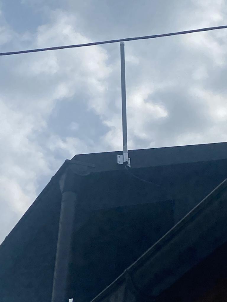
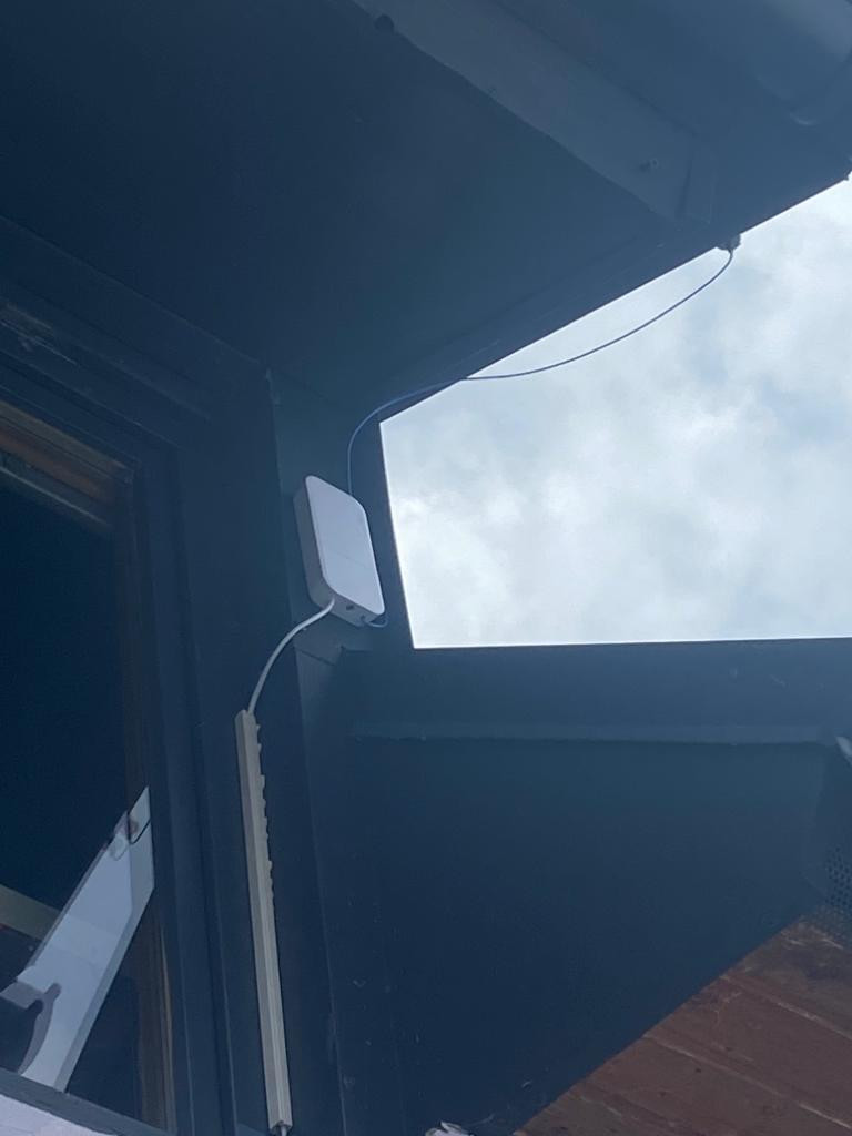
- Mount of the Antenna Antenne was mounted at the roof.
- Mount of the Router Before mounting the router a whole was drilled in the wall in order to put the network cable through. Using a cable channel the Ethernet cable was guided to the router.
Gateway configuration
The configuration the gateway is described in the official documentation of TTS or if you prefer videos I can highly recommend the videos from Alex(AEQWeb)[german].
MikroTIK
Once the router is powered on, you can connect to the network interface and configure this accordingly.
The Thing Stack (TTS)
The configuration can be done using TTS Console. Here you have to add the gateway information and do the neccessary configuration.
Test the communication with a #LoRaWAN client
The client code can be found here.
Side note: This will give you a rough overview about the software steps. In case you have not yet programmed in Arduino Studio and no experience there are several tutorials out there like e.g. randomnerdtutorial.
- Download the sample sketch
- Open the sketch with Arduino Studio
- Change FILLMEIN with the correct data of your sender
- define the correct PINS for your hardware board
- Select the correct hardware board = TTGO LoRa32 OLED V1
- Connect the board with your PC
- Select the correct serial port
- Upload the firmware
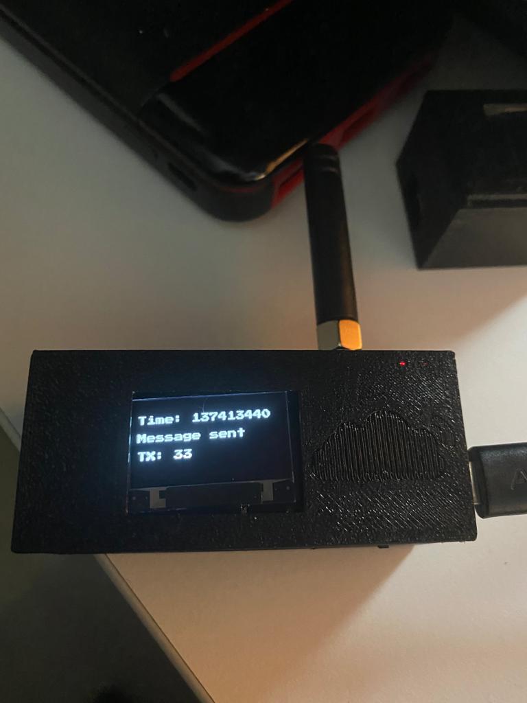
After uploading the client will connect to LoRa and start sending messages. The status should look somewhat like this:
Information how the device casing was created can be found at Instagram.
And you should retrieve the information in your router and in the TTS console:
Gateway is public available
The gateway is now up-running and available for public use. Subesequently, range tests will follow. Wish you a lot of fun and learning using #LoRaWan!
Lora MQTT Gateway
2021-03-06 #Blog | #LoRa | #LoRaGateway
LoRa (Long Range) is a proprietary low-power wide-area network modulation technique based on spread spectrum modulation techniques derived from chirp spread spectrum (CSS) technology. More information on that can be found in Wikipedia. This protocol can be utilized to create small private LoRa networks or one can use the TTS (=The Think Stack) to utilize LoRaWan. In this post, I would like to show you how one can made a LoRa Client (=Sender) and a LoRa Gateway which will publish the incoming messages into a defined #MQTT channel using a local WiFi connection. The solution is using AES-128 encryption on top LoRa and uses a defined message format.
What hardware do you need?
- 2 ESP32 based TTGO LoRa32 V2.1 _ 1,6 version 433/868/915 Mhz ESP32 LoRa OLED 0,96 Inch SD Karte Bluetooth WIFI wireless Modul ESP-32 SMA
Platform
You need one running MQTT broker. You can find a guide here.
Architecture overview
Before we come to the implementation of the client and the gateway, let’s check what we would like to build.
As you can see in the drawing, the LoRa client can be used to gather sensor data and send them via LoRa to the gateway in a secure way. The gateway will then forward the message to the local MQTT broker via WiFi. The consumers will then be able to get the information from the defined MQTT channel. Awesome, right?
We are going to create a firmware for the LoRa client and the LoRa gateway in order to communicate to each other via LoRa. As LoRa is a public channel, everyone can send messages and of course, receive messages within the defined frequency band. So, if you do not secure your information, this can be read easily be everyone in (best case) around 15 km! With this in mind, both parties are using AES-128 encryption with a shared secret key.
Message format
Based on the idea from Alex (see his post) the message is in the following format
LORACLIENTNAME<DELIMITER>DATAATTRIBUT1<DELIMITER><DATAATTRIUB2><DELIMITER><...><DELIMITER>
The provided client sample will send a message with following format:
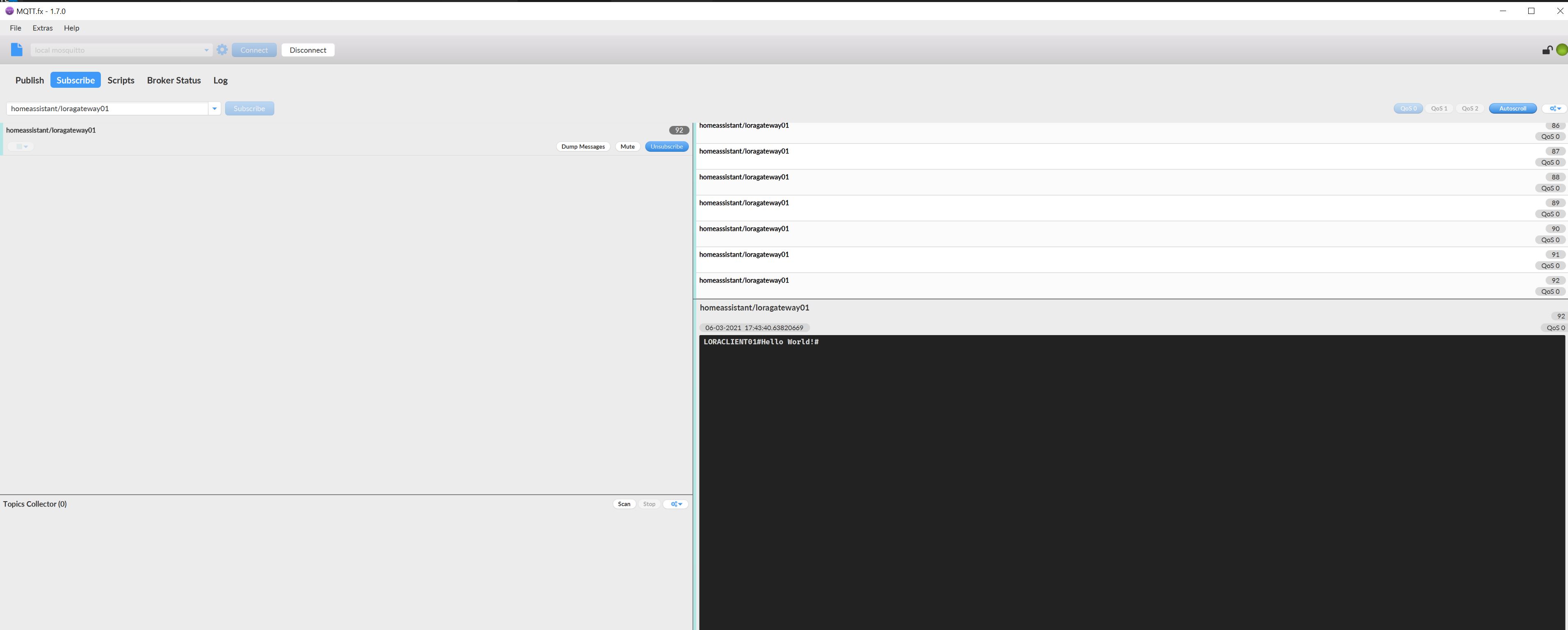
LORACLIENT01#Hello World!#
Lora Client
The client code can be found here.
Side note: This will give you a rough overview about the software steps. In case you have not yet programmed in Arduino Studio and no experience there are several tutorials out there like e.g. randomnerdtutorial.
- Download the sample sketch
- Open the sketch with Arduino Studio
- Add your ENCRYPTION KEY and define your Client ID
- Select the correct hardware board = TTGO LoRa32 OLED V1
- Connect the board with your PC
- Select the correct serial port
- Upload the firmware
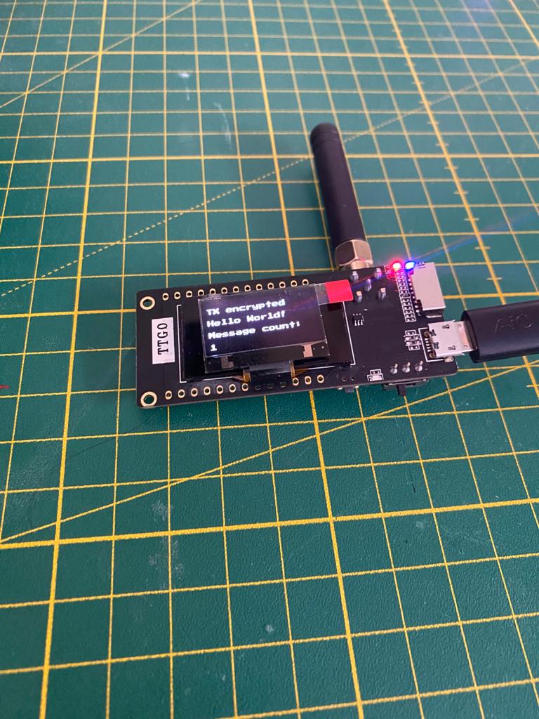
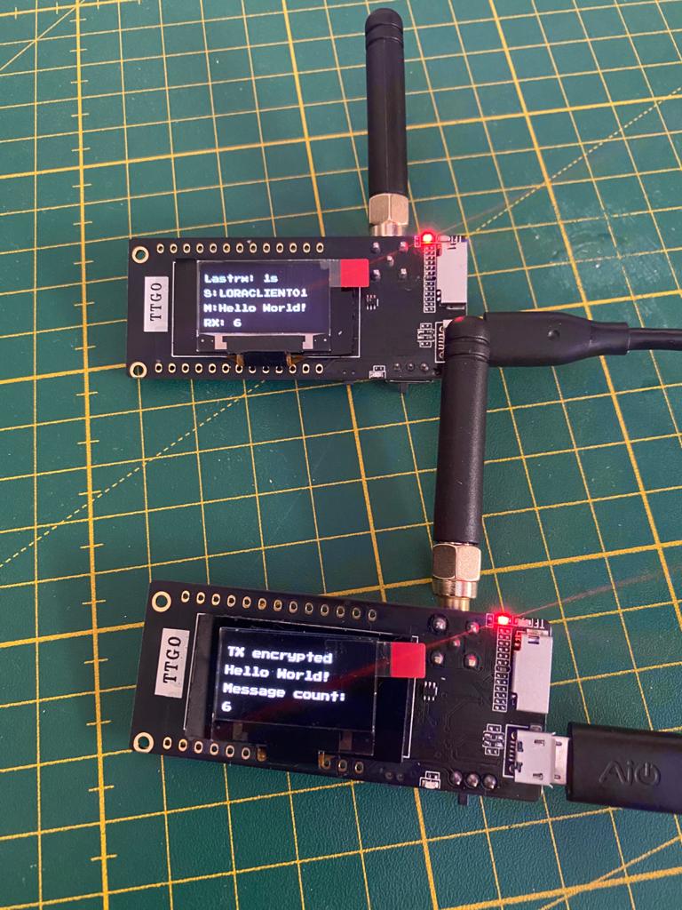
After uploading the client will connect to LoRa and start sending messages. The status should look somewhat like this:
Lora Gateway
The client code can be found here.
- Download the sample sketch
- Open the sketch with Arduino Studio
- Add the needed information like WiFi SSID, creds, aso. in secrets.h and ensure that you are using the same ENCRYPTION KEY than the client (otherwise the messages cannot be decrypted)
- Select the correct hardware board = TTGO LoRa32 OLED V1
- Connect the board with your PC
- Select the correct serial port
- Upload the firmware
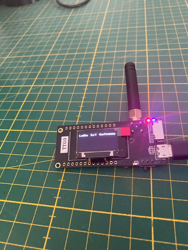
After uploading the client will connect to the defined WiFi, to MQTT borker and LoRa and will start to publish messages if there are any to forward.
Result
The client will send in a defined interval “Hello World!” and increase the message counter. You can see this on the display on the client. The gateway will receive the message, decrypt it and forward the message to the MQTT broker and display the message a receive counter and the sender on the display.
In order to check if you also receive MQTT messages you can use MQTT.fx, connect to the broker and subscribe to your defined LoRa gateway channel.
Using Power Automate & Home Assistant to trigger a mailbox indicator
2021-03-05 #Blog | #PowerAutomate | #MailboxIndicator
A while back I created a Mailbox indicator. This blog post will describe you the necessary steps to trigger the mailbox indicator whenever a mail arrives in your M365 Outlook using #HomeAssistant and #PowerAutomate to talk to your mail indicator device.
What hardware do you need?
- ESP8266 or ESP32 based board (ideally in the form factor of a WEMOS or TTGO mini)
- SG 90 Servo
- 3D Printed mailbox from Thingiverse
Hardware - Put the stuff together
- Solder the VCC cable to the 3.3V pin of the MCU, the GND cable to the ground of the MUC and the data cable with the GPIO pin of your choice (e.g. D5)
- Print the parts and follow the assembly instructions from Thingiverse
Platform - Home Assistant
In order to run the whole thing, you need to have a running Home Assistant instance including MQTT broker. You can find several guides and howto’s like this one in the net.
Software - flash the controller
Side note: This will give you a rough overview about the software steps. In case you have not yet programmed in Arduino Studio and no experience there are several tutorials out there like e.g. randomnerdtutorial.
- Download the sample sketch from github.
- Open the sketch with Arduino Studio
- Add your wifi credentials and mqtt connection details
- Select the correct hardware board (e.g. WEMOS D1 Mini ESP32)
- Connect the board with your PC
- Select the correct serial port
- Upload the firmware
- Test it: Try if the defined mqtt channel receives signal, when there is no contact and when there is contact. To do this, you just need to run a MQTT software like MQTT.fx, connect to the broker and subscribe to the corresponding channel. If everything is configured properly then you’ll receive the JSON messages. In case you don’t receive messages, you have to check the wiring as well as the configuration parameters in your secrets.h. Furthermore, you can connect to the controller via putty and check the serial print for more information, add debug information to the software, etc.
Home Assistant configuration
If all works well and you receive messages in the defined channel, you can do the last steps in order to add the sensor to your smart home platform.
Open the scripts.yaml of your Home Assistant instance and add following sensor to the sensor configuration:
  maibox_indicator_1_trigger:
  alias: Mailbox Indicator 1 Trigger
  sequence:
  - service: mqtt.publish
    data:
      topic: homeassistant/mailbox1/set
      payload: ha_toogle
  mode: single
Then add the sensor to your Dashboard and you’ll see something like this:

You can then test the trigger manually and the Mailbox indicator flag should move up and down after each execution.
Power Automate configuration
- Open the browser and enter the address www.office.com
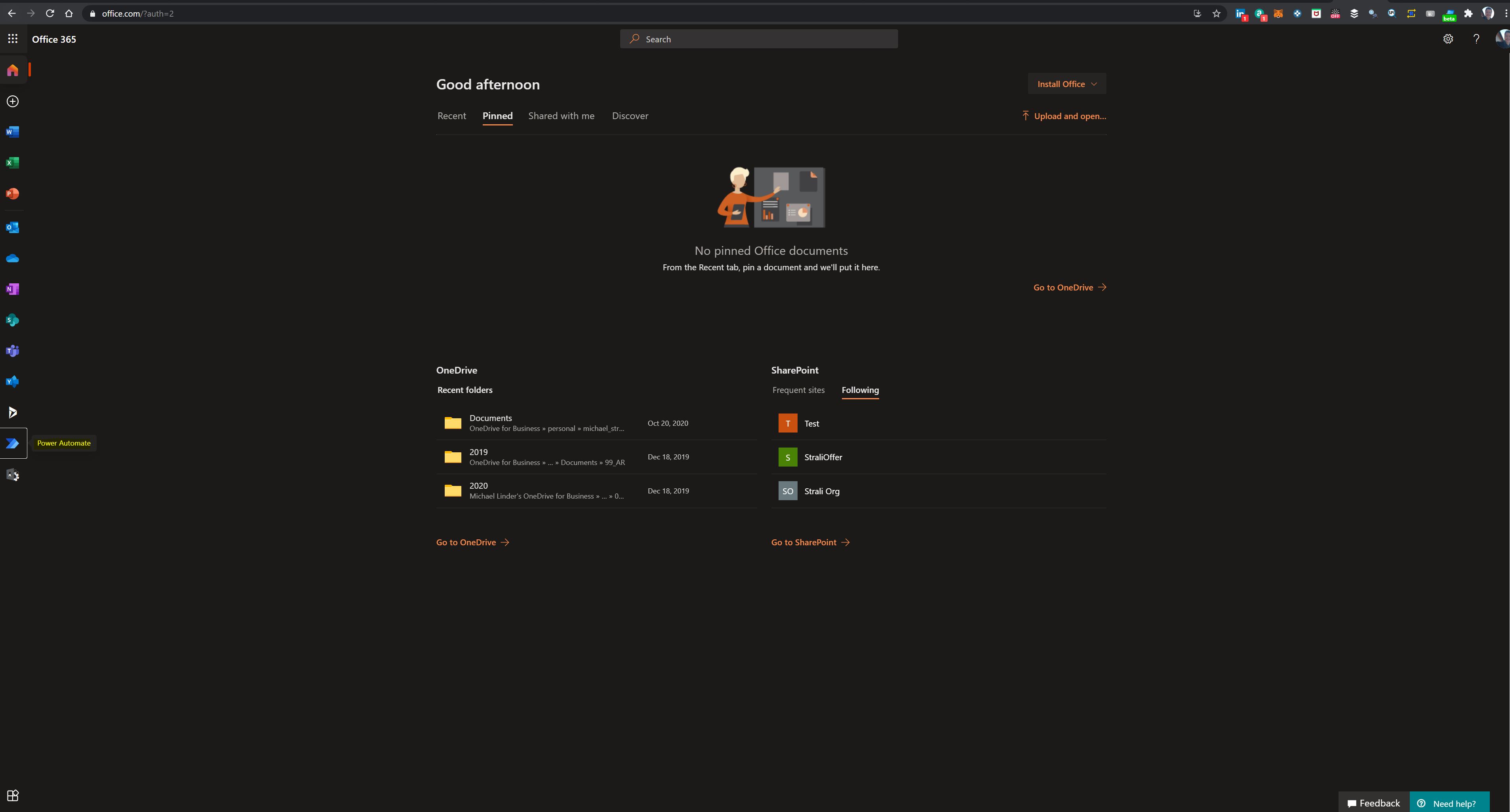
- If you have no office account create one and login
- Click “Power Automate”
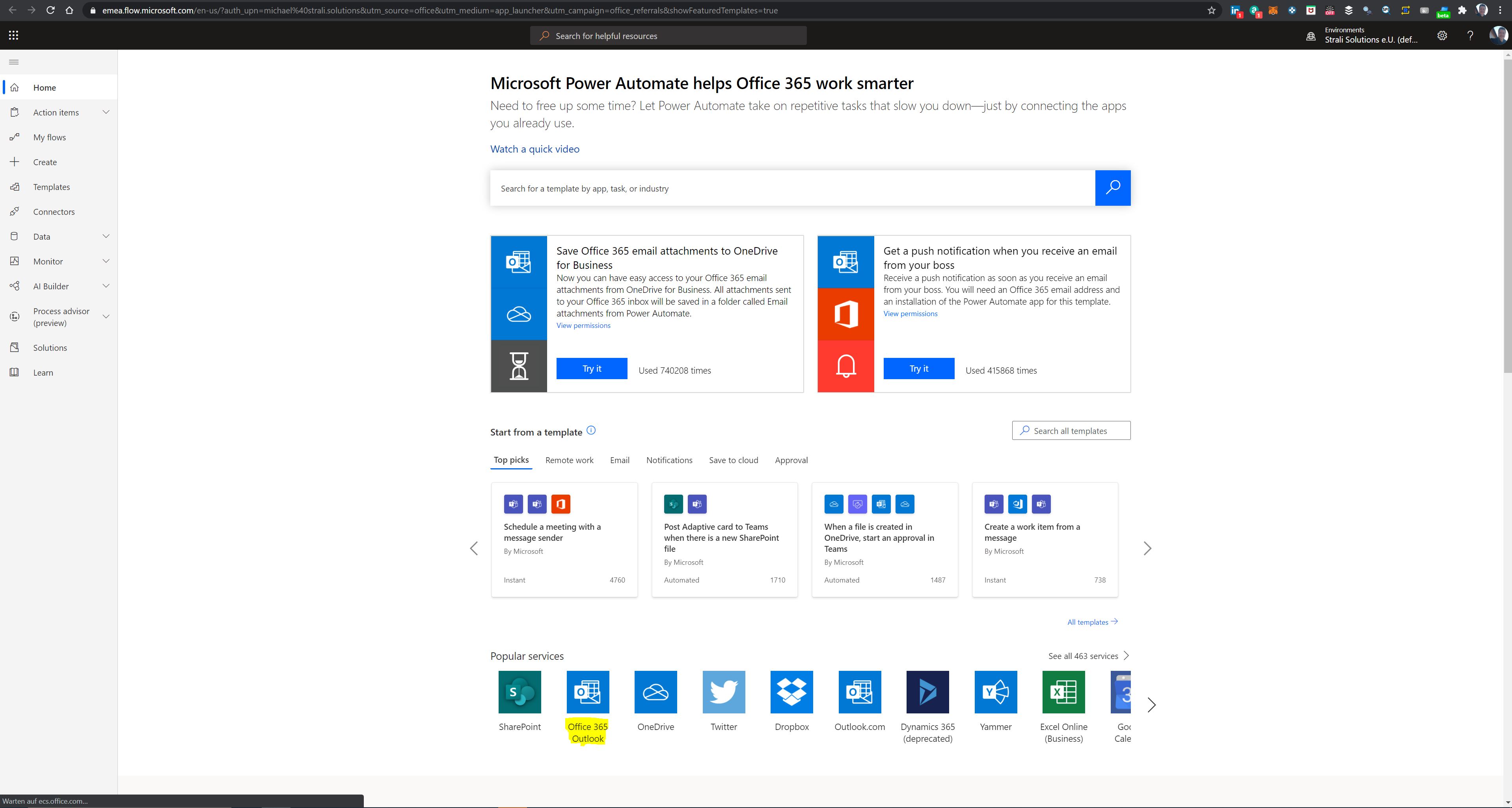
- Click “Office 365 Outlook” under “Popular Services”
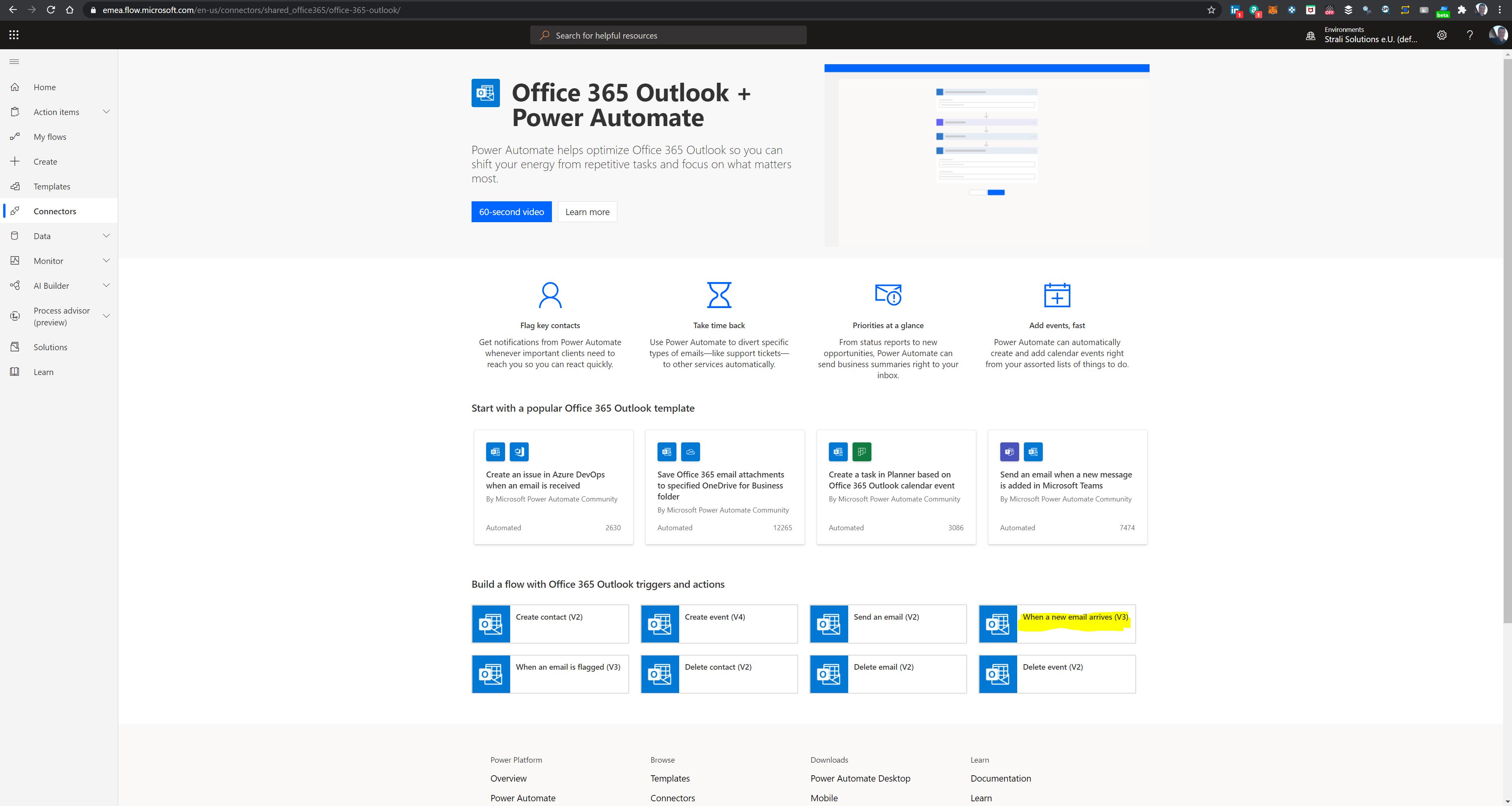
- Click “When new mail arrives”
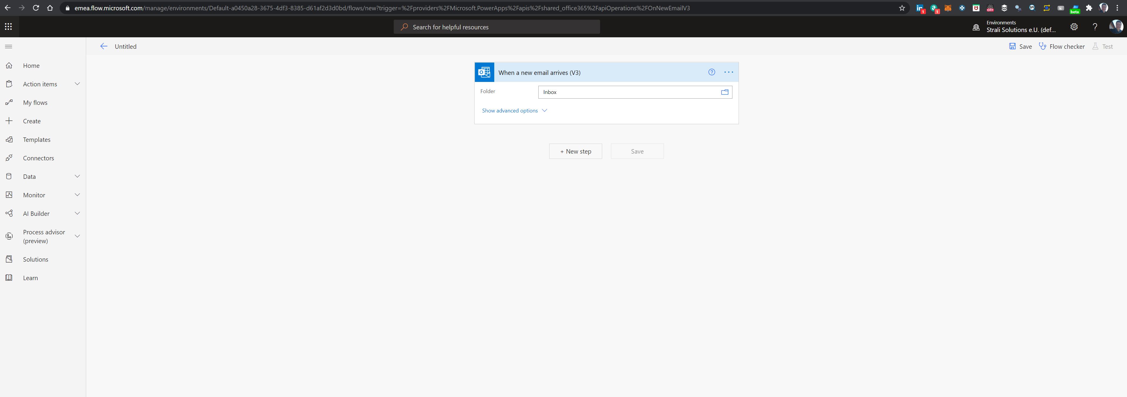
- Choose Folder “inbox” and click next
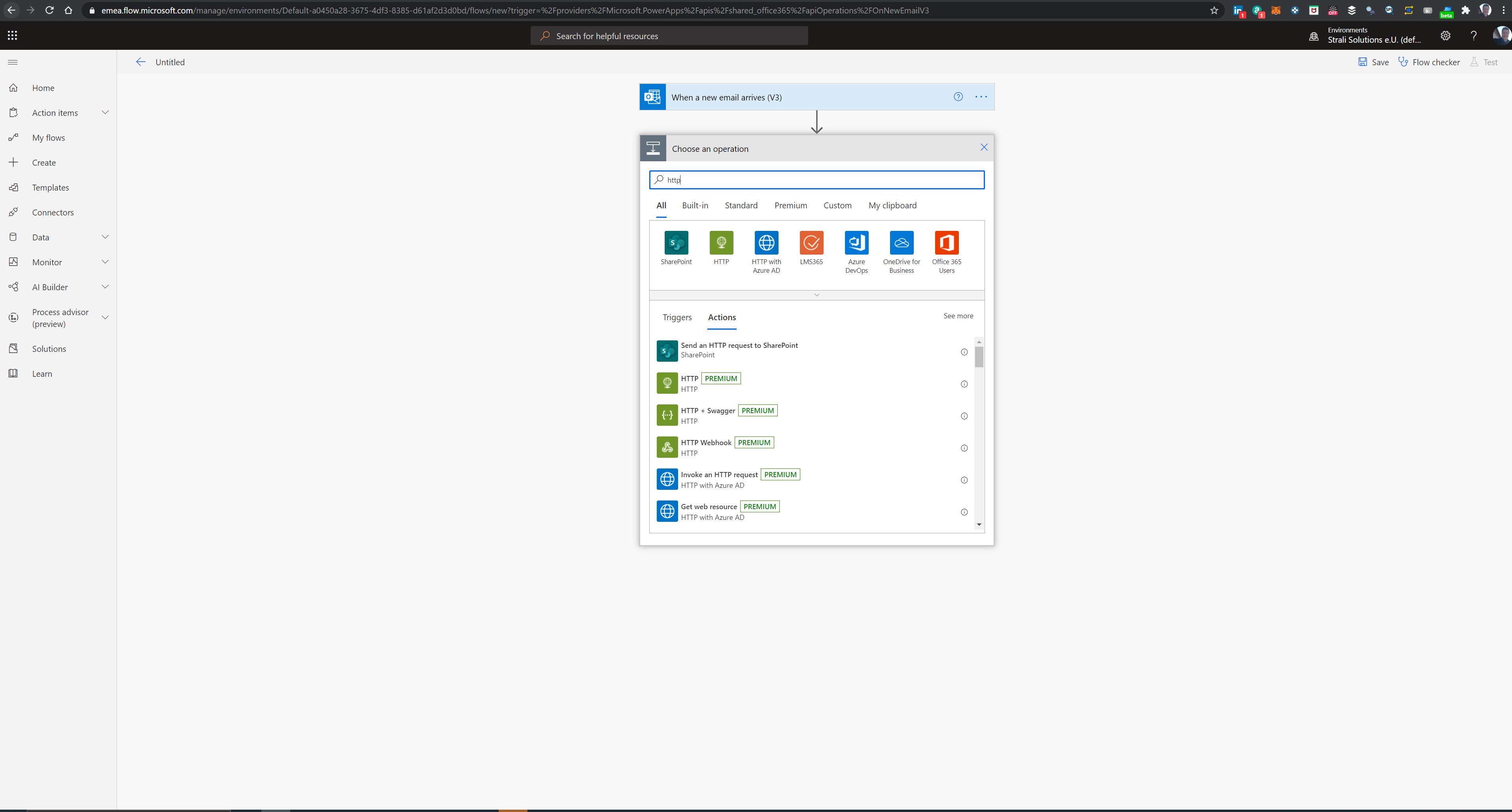
- Search for “http” operation and choose this (Note: This is a premium service and after a trail period this will charges will be there. More info on pricing here Power Automate pricing)
- Enter the REST API configuration:
- Choose Method POST
- Enter the url https://
/api/services/script/turn_on and change with your real dns name - Add header Authorization and copy your long lived access token there (be careful to not expose this information!)
- Add Body
"entity_id": "script.maibox_indicator_1_trigger"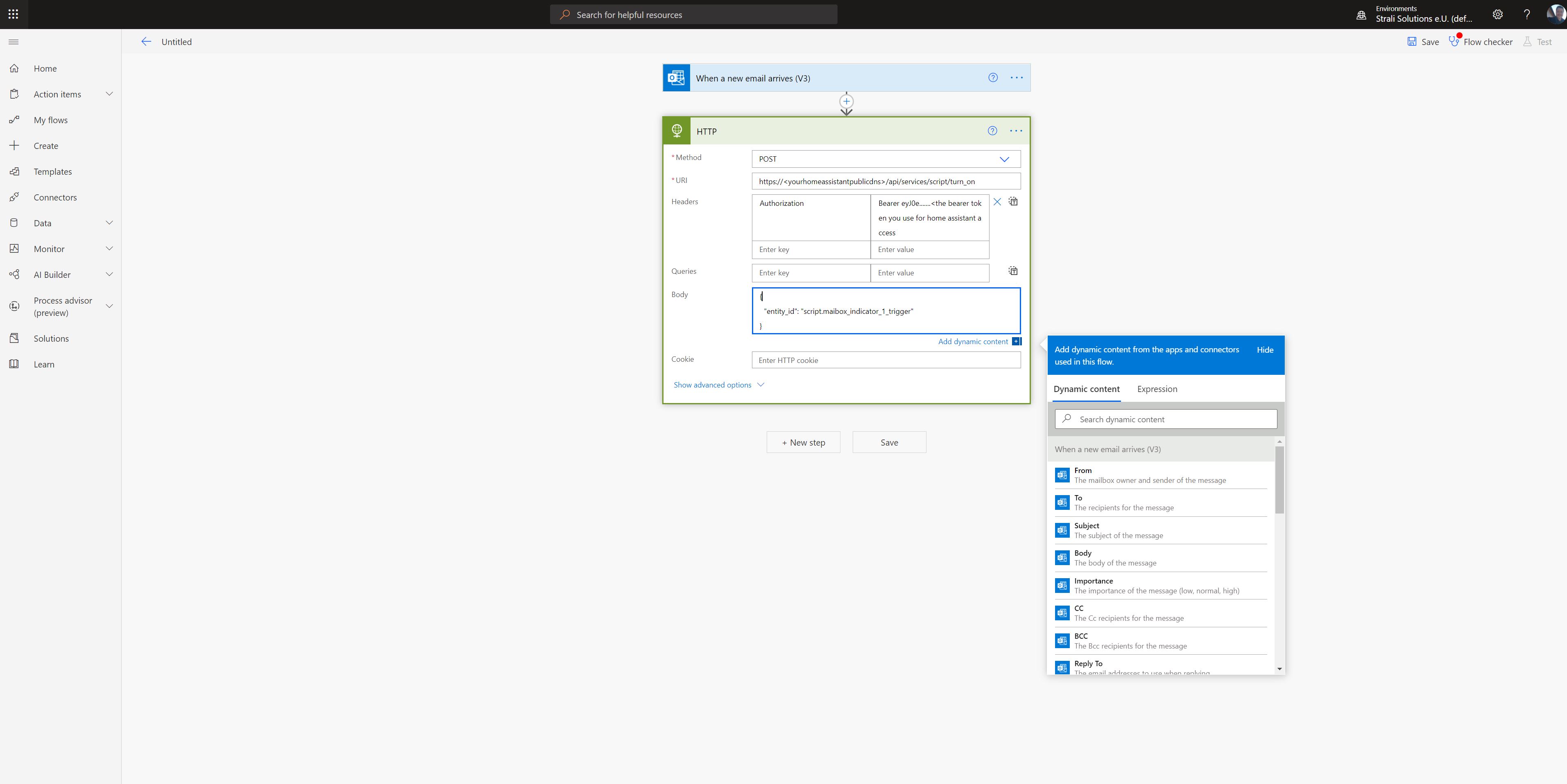
- Test it manually by sending a mail to your mailbox
- The flow should be in state success and the mailbox trigger fired
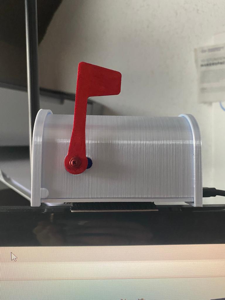
Congratulations, you have successfully created and configured your mailbox indicator :)
Door/Window Sensor
2021-03-04 #Blog | #Windowsensor
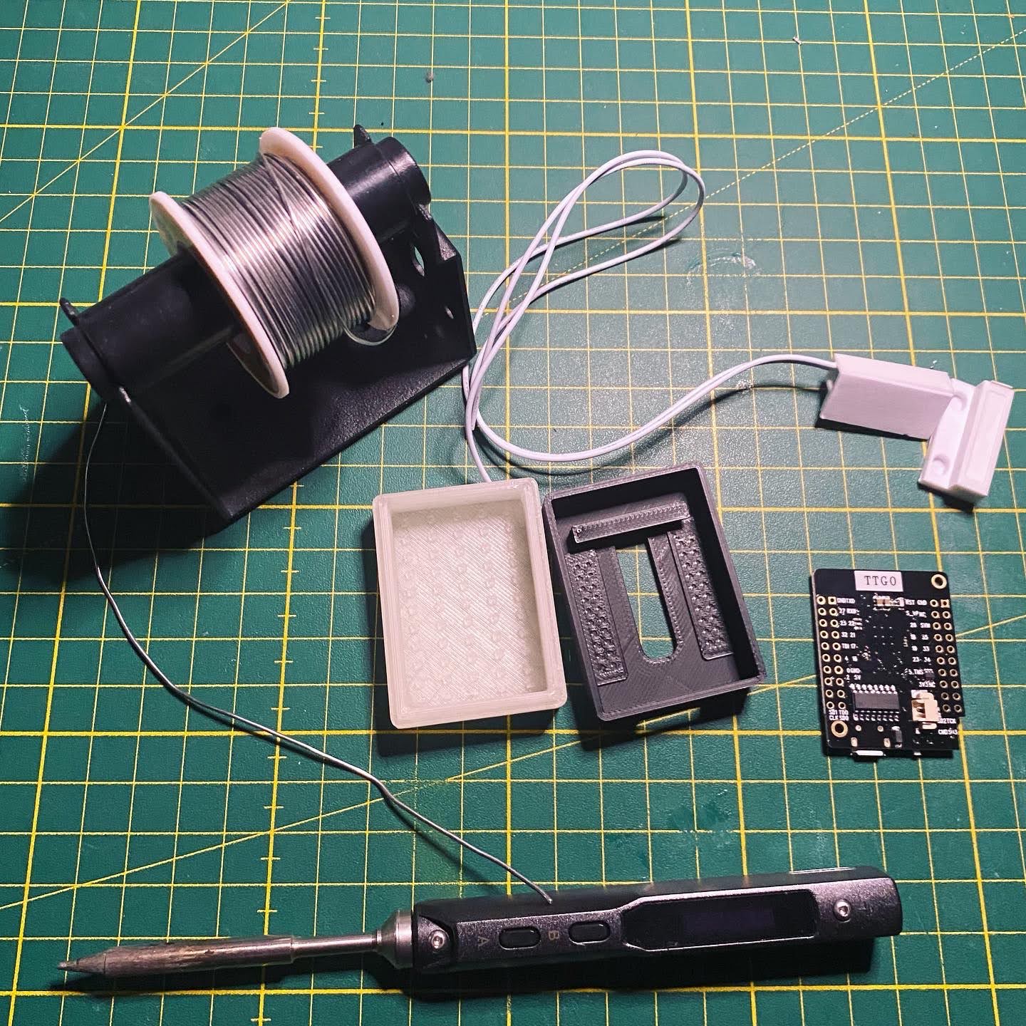
Do you want to create your own door/window sensor and add to #HomeAssistant.
Great! So, here we go!
What hardware do you need?
- ESP8266 or ESP32 based board (ideally in the form factor of a WEMOS or TTGO mini)
- Reed Switch
- 3D Printed case
Hardware - Put the stuff together
- Solder the reed switch to the ESP board => one end to the 3.3V PIN, the other to a GPIO PIN (e.g. PIN 16)
- (Modify) and print the case from Tinkercad and put the board in
Platform - Home Assistant
In order to run the whole thing, you need to have a running Home Assistant instance including MQTT broker. You can find several guides and howto’s like this one in the net.
Software - flash the controller
Side note: This will give you a rough overview about the software steps. In case you have not yet programmed in Arduino Studio and no experience there are several tutorials out there like e.g. randomnerdtutorial.
- Download the sample sketch from github.
- Open the sketch with Arduino Studio
- Open the secrets.h file and add your wifi credentials and mqtt connection details
- Select the correct hardware board (e.g. WEMOS D1 Mini ESP32)
- Connect the board with your PC
- Select the correct serial port
- Upload the firmware
Mount the hardware and test
Now mount the hardware near the window in order that the switch has contact when window is closed and no contact when the window is open. Try if the defined mqtt channel receives signal, when there is no contact and when there is contact. To do this, you just need to run a MQTT software like MQTT.fx, connect to the broker and subscribe to the corresponding channel. If everything is configured properly then you’ll receive the JSON messages. In case you don’t receive messages, you have to check the wiring as well as the configuration parameters in your secrets.h. Furthermore, you can connect to the controller via putty and check the serial print for more information, add debug information to the software, etc.
Home Assistant configuration
If all works well and you receive messages in the defined channel, you can do the last steps in order to add the sensor to your smart home platform.
Open the configuration.yaml of your Home Assistant instance and add following sensor to the sensor configuration:
  - platform: mqtt
    name: "YOUR WINDOW/DOOR SENSOR NAME"
    state_topic: "homeassistant/doorzone1/alarm"
    value_template: 'Window '
After that restart your Home Assistant.
Then add the sensor to your Dashboard and you’ll see something like this:

Congratulations, you created your own window/door sensor!
Spycam
Today I found the time to investigate a Chinese manufactured spycam pruchased months ago on AliExpress (for around 15€). The cam is hidden in a digital alarm clock and barely recognizable.
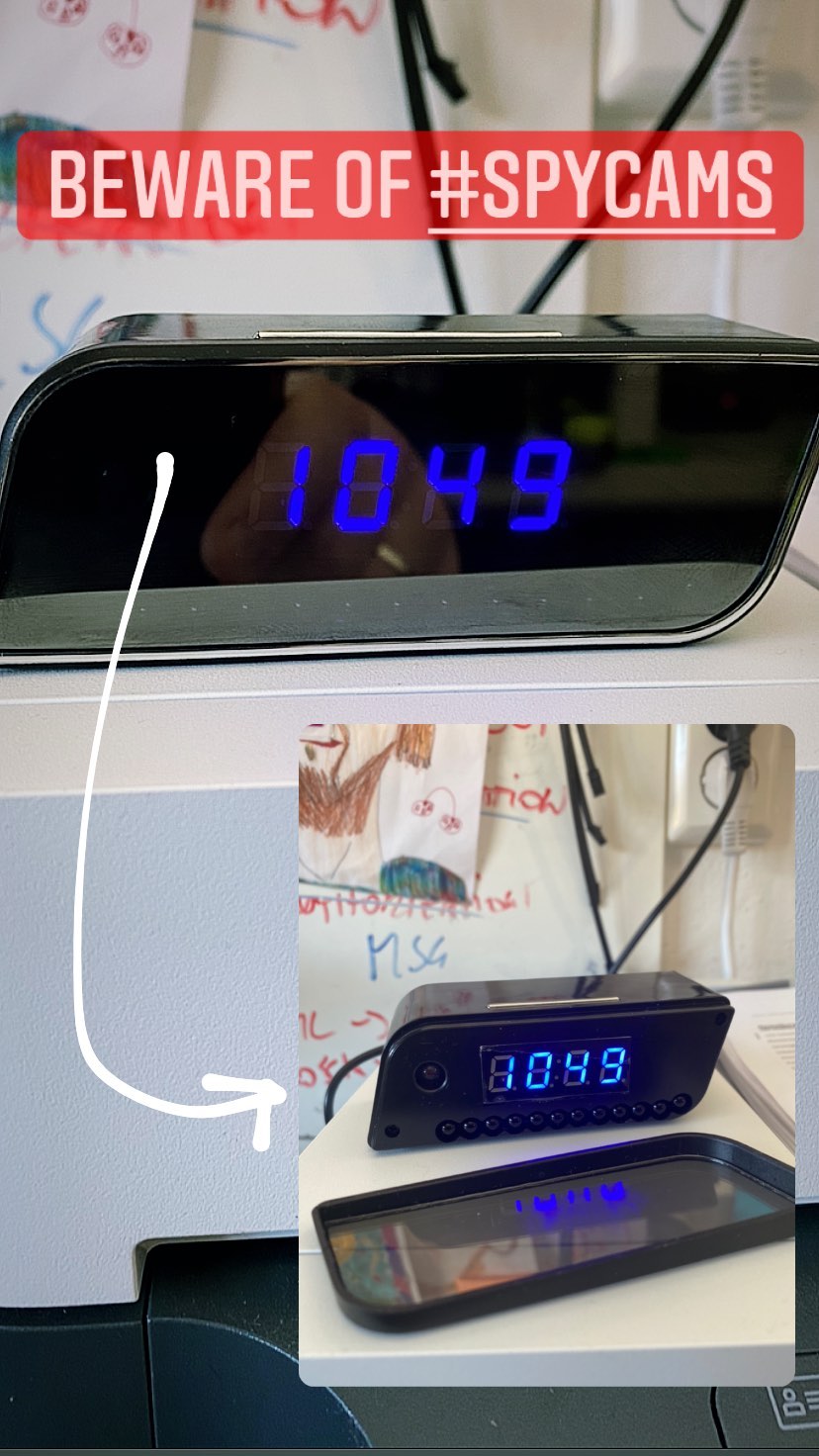
After powering the device with the mini USB cable, the clock shows no time. So, in order to wake the whole system up, one has to grab the smartphone and install the V380 pro app for configuring the spy. After installing the app, one has to connect to the camera directly via WIFI and add the local WIFI credentials. Once this was done, the alarm clock display shows the current time and also you can connect to the camera. Next, I installed BlueStacks, WireShark and V380 pro in BlueStacks to prepare all the tools to find how the app connects to camera. To investigate WireShark and V380 pro were started in parallel to check the network traffic. Bam, surprise (or not)!
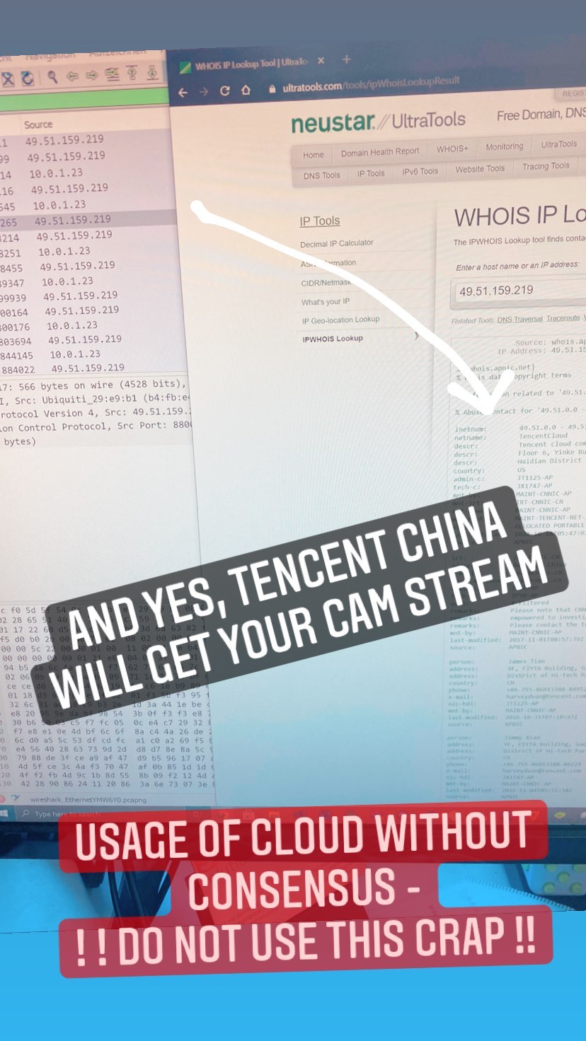
Although, I did not create a cloud user and gave no consensus to explicitly use cloud services the app is using a direct connection to Tencent to play show the video and play the sound. In order to break the connection, I completely blocked the discovered Tencent IP from out and inbound. Guess what, this thing is using a fallback then :-) However, I did not find a way to use a direct WIFI connection to this camera. With this configuration and the direct streaming from picture and voice from home to China and back, I cannot recommend to anyone to use this. However, will further discover, maybe there is a native way, or one can flash the cam with other firmware. The update might follow.